Lab 9: Mapping
Lab 9
Goals
-
This lab aims to map the room by rotating the robot at several known positions and recording distance measurements with the ToF sensor. The collected data are combined in a global coordinate frame to produce a usable map of the environment.
IMU / gyro-based orientation control
In this lab, the robot uses IMU-based yaw feedback rather than open-loop turning. The gyroscope z-axis is first bias-calibrated while the robot is stationary, and the corrected angular velocity is then integrated over time to estimate the current yaw angle. During scanning, a PID controller computes the yaw error between the target heading and the measured heading, and converts this error into a signed turning PWM command so that the robot rotates to each desired angle and briefly settles before taking a ToF measurement.
1. System initialization and sensor setup
The firmware first initializes the ToF sensor, IMU, and BLE service. The ToF sensor is configured in short-distance mode with a 50 ms timing budget, while the IMU is initialized over I2C. BLE is then used as the command-and-log interface between the robot and the notebook.
static void init_tof_or_die()
{
  int err = tof.begin();
  if (err != 0) {
    while (1) { delay(100); }
  }

  tof.setDistanceModeShort();
  tof.setTimingBudgetInMs(50);
  tof.startRanging();
}

static void init_imu_or_die()
{
  bool imu_ok = false;

  for (int k = 0; k < 5; k++)
  {
    imu.begin(Wire, 0x68);
    if (imu.status == ICM_20948_Stat_Ok)
    {
      imu_ok = true;
      break;
    }
    delay(50);
  }

  if (!imu_ok) {
    while (1) { delay(100); }
  }
}
2. Gyro bias calibration and yaw estimation
Before any controlled turning, the robot performs a gyro bias calibration while remaining still. Afterward, the corrected gyroscope z-axis reading is integrated over time to obtain the robot's yaw angle. This yaw estimate is used as the feedback variable for orientation control throughout the scan.
static void calibrate_gyro_bias()
{
  float sum_gz = 0.0f;
  int valid_count = 0;

  for (int k = 0; k < 30; k++)
  {
    float gz_dummy;
    imu_read_gyro_z(gz_dummy);
    delay(5);
  }

  while (valid_count < GYRO_BIAS_SAMPLES)
  {
    BLE.poll();

    float gz;
    if (imu_read_gyro_z(gz))
    {
      sum_gz += gz;
      valid_count++;
    }

    delay(5);
  }

  gyro_z_bias_dps = sum_gz / (float)valid_count;
  reset_yaw_state();
}

static void update_imu_state()
{
  float gz_now;
  if (!imu_read_gyro_z(gz_now)) return;

  unsigned long now_ms = millis();

  gyro_z_raw_dps = gz_now;
  gyro_z_corr_dps = gyro_z_raw_dps - gyro_z_bias_dps;

  if (imu_last_sample_time_ms == 0)
  {
    imu_last_sample_time_ms = now_ms;
    imu_has_valid = true;
    return;
  }

  unsigned long dt_ms = now_ms - imu_last_sample_time_ms;
  if (dt_ms == 0) return;

  float dt = ((float)dt_ms) / 1000.0f;
  yaw_deg += gyro_z_corr_dps * dt;

  imu_last_sample_time_ms = now_ms;
  imu_has_valid = true;
}
3. Yaw PID orientation controller
A PID controller is used to rotate the robot to a target heading. The controller computes the wrapped heading error, applies proportional, integral, and derivative terms, and then converts the control output into a signed PWM command for in-place turning. Once the heading error enters a small stop band, the robot actively brakes and holds position for sampling.
static void yaw_pid_control_step()
{
  if (!imu_has_valid)
  {
    stop_all_turning();
    motor_active_brake();
    return;
  }

  yaw_error_deg = wrap_angle_deg(yaw_target_deg - yaw_deg);

  if (fabs(yaw_error_deg) <= STOP_BAND_DEG)
  {
    pwm_cmd_signed = 0;
    motor_active_brake();
    return;
  }

  float dt_i = ((float)yaw_ctrl_period_ms) / 1000.0f;

  yaw_P_term = Kp_yaw * yaw_error_deg;
  yaw_error_integral += yaw_error_deg * dt_i;

  if (yaw_error_integral > YAW_INTEGRAL_MAX) yaw_error_integral = YAW_INTEGRAL_MAX;
  if (yaw_error_integral < -YAW_INTEGRAL_MAX) yaw_error_integral = -YAW_INTEGRAL_MAX;

  yaw_I_term = Ki_yaw * yaw_error_integral;
  yaw_D_term = -Kd_yaw * gyro_z_corr_dps;
  yaw_control_u = yaw_P_term + yaw_I_term + yaw_D_term;

  int pwm = PWM_TURN_MIN + (int)fabs(yaw_control_u);
  if (pwm > PWM_TURN_MAX) pwm = PWM_TURN_MAX;

  if (yaw_control_u > 0) pwm_cmd_signed = pwm;
  else pwm_cmd_signed = -pwm;

  apply_turn_control(pwm_cmd_signed);
}
4. Lab 9 mapping scan state machine
The mapping routine is organized as a simple state machine. For each scan point, the robot generates a sequence of target angles, turns to each angle using the yaw PID controller, waits for a short settle period, and then records the current yaw, ToF range, gyroscope value, PWM command, and sensor status. This process repeats until the full angular span is completed.
enum MappingStage
{
  MAP_IDLE = 0,
  MAP_SETTLING = 1,
  MAP_TURNING = 2,
  MAP_DONE = 3
};

static void mapping_start_scan(float step_deg_in, int settle_ms_in, float total_span_deg_in, int turn_dir_in)
{
  stop_all_control_and_brake();

  mapping_step_deg = step_deg_in;
  mapping_settle_ms = (unsigned long)settle_ms_in;
  mapping_total_span_deg = total_span_deg_in;
  mapping_turn_dir = (turn_dir_in >= 0) ? 1 : -1;
  mapping_total_points = (int)floor(mapping_total_span_deg / mapping_step_deg + 0.5f) + 1;

  mapping_log_len = 0;
  mapping_current_index = 0;
  mapping_start_yaw_deg = yaw_deg;
  mapping_start_ms = millis();
  mapping_active = true;
  mapping_stage = MAP_IDLE;

  mapping_prepare_next_target(mapping_start_ms);
}

static void mapping_service()
{
  if (!mapping_active) return;

  unsigned long now_ms = millis();

  if (mapping_stage == MAP_TURNING)
  {
    if ((now_ms - yaw_last_ctrl_ms) >= yaw_ctrl_period_ms)
    {
      yaw_last_ctrl_ms = now_ms;
      yaw_pid_control_step();
    }

    float err = wrap_angle_deg(yaw_target_deg - yaw_deg);
    if (fabs(err) <= STOP_BAND_DEG)
    {
      motor_active_brake();
      pwm_cmd_signed = 0;
      mapping_stage = MAP_SETTLING;
      mapping_settle_start_ms = now_ms;
    }
  }
  else if (mapping_stage == MAP_SETTLING)
  {
    motor_active_brake();
    pwm_cmd_signed = 0;

    if ((now_ms - mapping_settle_start_ms) >= mapping_settle_ms)
    {
      mapping_append_log(now_ms - mapping_start_ms);
      mapping_current_index++;
      mapping_prepare_next_target(now_ms);
    }
  }
}
5. BLE command interface and log upload
BLE is used to trigger calibration, yaw reset, mapping scan start, and log transmission. The robot stores scan data in a buffer and uploads it in CSV form after the scan. This made it straightforward to collect raw data in the notebook and convert it into polar plots and merged global scatter plots during post-processing.
enum CommandTypes
{
  CALIB_GYRO_BIAS    = 20,
  RESET_YAW          = 24,
  START_YAW_PID_CTRL = 32,
  START_MAPPING_SCAN = 35,
  STOP_MAPPING_SCAN  = 36,
  SEND_MAPPING_LOG   = 37
};

static void send_mapping_log_csv()
{
  int n = mapping_log_len;

  ble_send_csv_begin(
    n,
    "idx,time_ms,target_mdeg,yaw_mdeg,tof_centi_mm,gz_mdps,pwm_signed,tof_status"
  );

  for (int i = 0; i < n; i++)
  {
    char msg[MAX_MSG_SIZE];
    snprintf(msg, sizeof(msg),
             "%d,%lu,%ld,%ld,%ld,%ld,%d,%d",
             mapping_idx_buf[i],
             mapping_t_ms_buf[i],
             (long)lroundf(mapping_target_deg_buf[i] * 1000.0f),
             (long)lroundf(mapping_yaw_deg_buf[i] * 1000.0f),
             (long)lroundf(mapping_tof_mm_buf[i] * 100.0f),
             (long)lroundf(mapping_gz_dps_buf[i] * 1000.0f),
             mapping_pwm_buf[i],
             mapping_tof_status_buf[i]);

    ble_tx_string(msg, BLE_TX_LINE_DELAY_MS);
  }

  send_end_marker();
}
2. Experimental Procedure and Data Collection
The robot was placed at several marked locations in the lab and performed a stepwise scanning motion at each position. For every scan, the gyroscope bias was calibrated, the yaw angle was reset, and the robot rotated around its vertical axis under IMU-based orientation control while the ToF sensor recorded distance measurements at discrete headings. After each scan, the logged data were uploaded through BLE and saved for later post-processing, including single-point plots and global map fusion.
3.1 Single-Point Scan Results
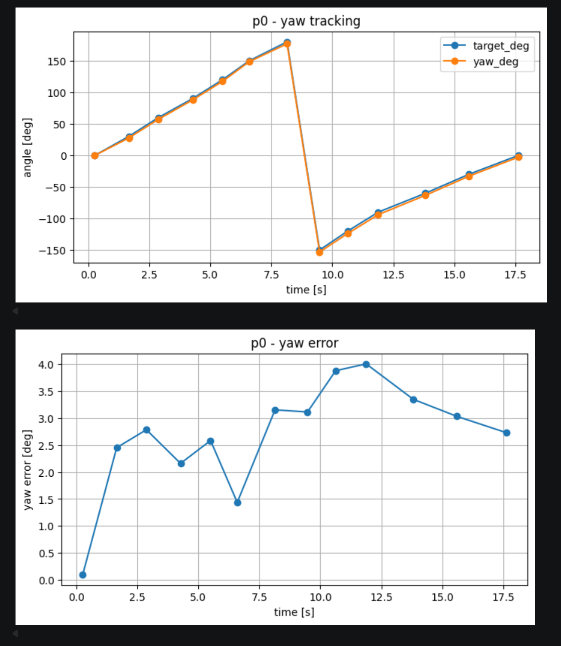
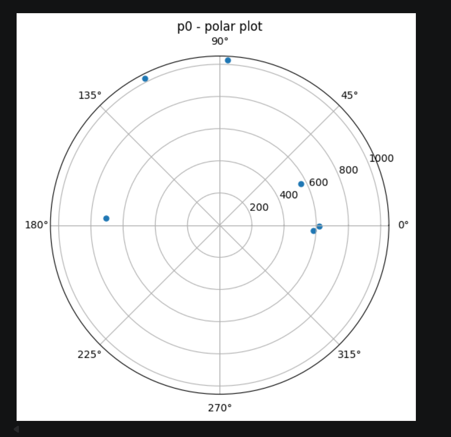
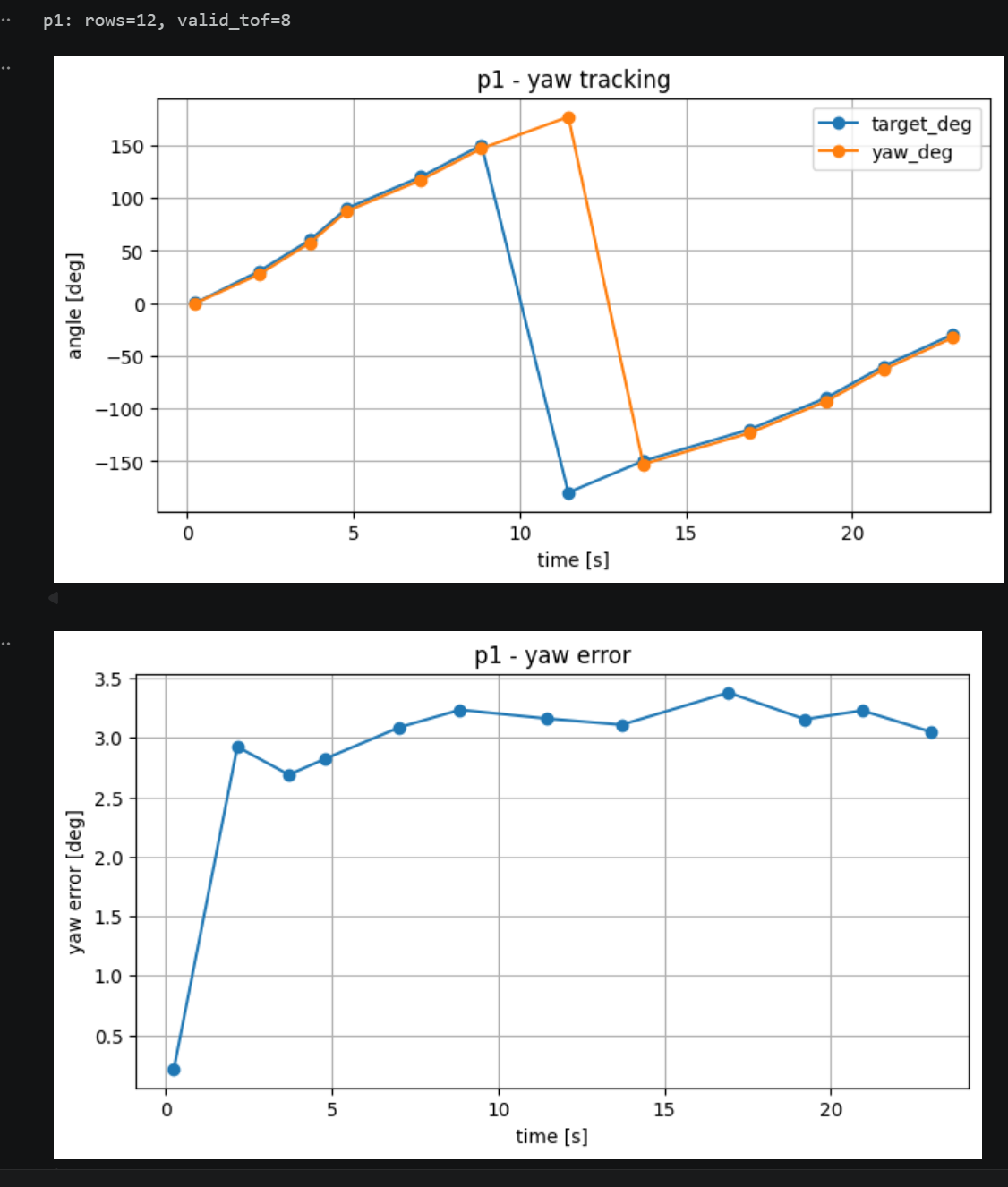
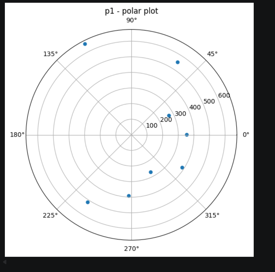
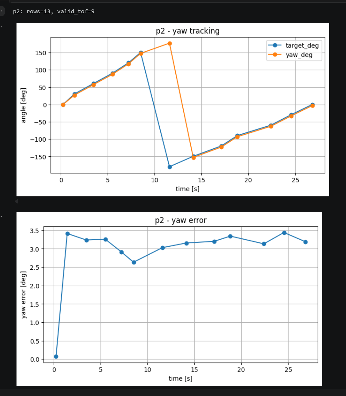
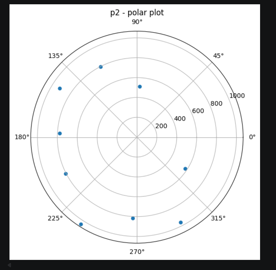
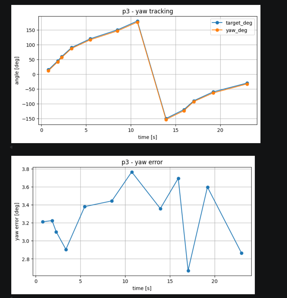
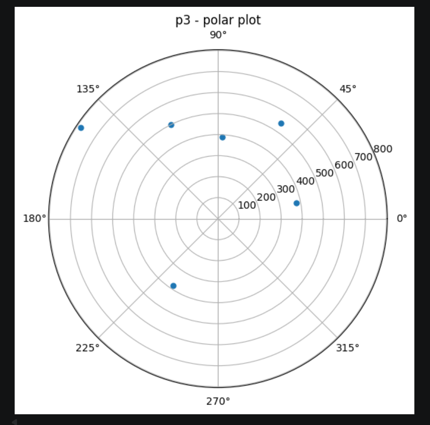
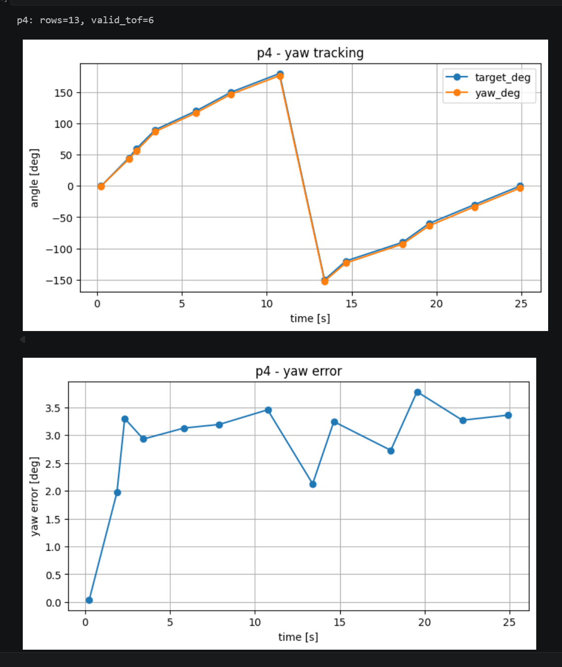
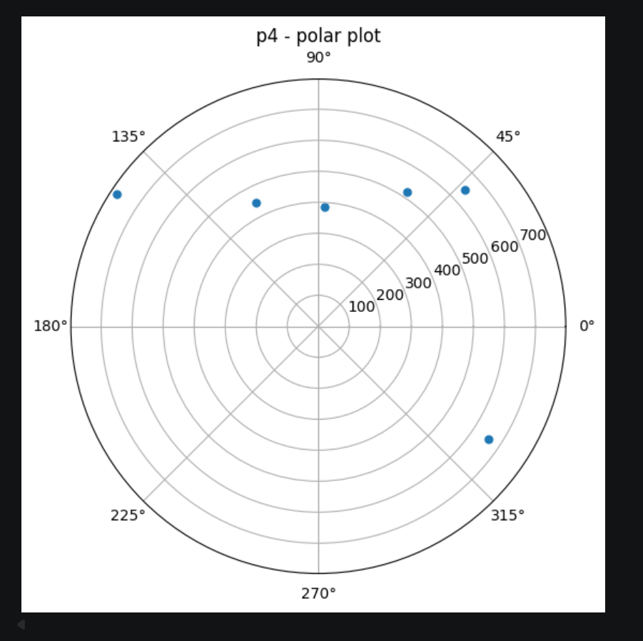
Figures 1–10 show the single-point scan results collected at the five marked locations. For each scan, the yaw tracking plot compares the target heading sequence with the measured yaw angle, while the corresponding polar plot visualizes the valid ToF readings in angular space. Across all scan positions, the robot was able to follow the desired stepwise heading sequence closely, and the yaw error remained within only a few degrees in most cases. Although some headings produced missing or invalid ToF measurements, each scan still captured useful local geometric information and provided a valid input for the later global map fusion step.
In particular, the yaw tracking results indicate that the IMU-based orientation controller was stable enough for discrete-angle scanning, even through the wrap-around transition near \(\pm180^\circ\). The polar plots also show that each position contributed a different local view of the room, which is why combining multiple scans from different marked locations is important for reconstructing the overall map.
3.2 Global Frame Transformation and Merged Map
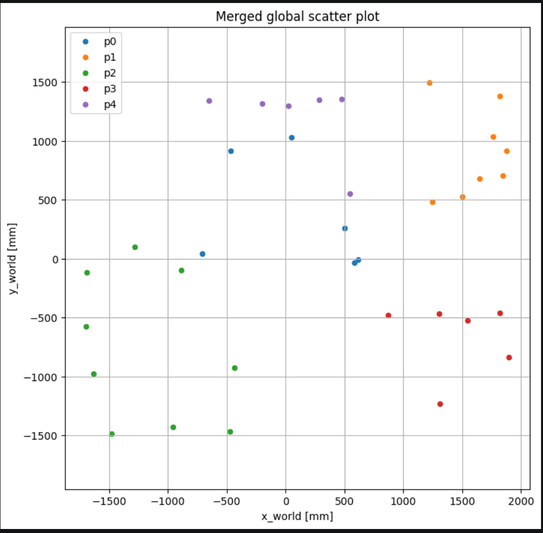
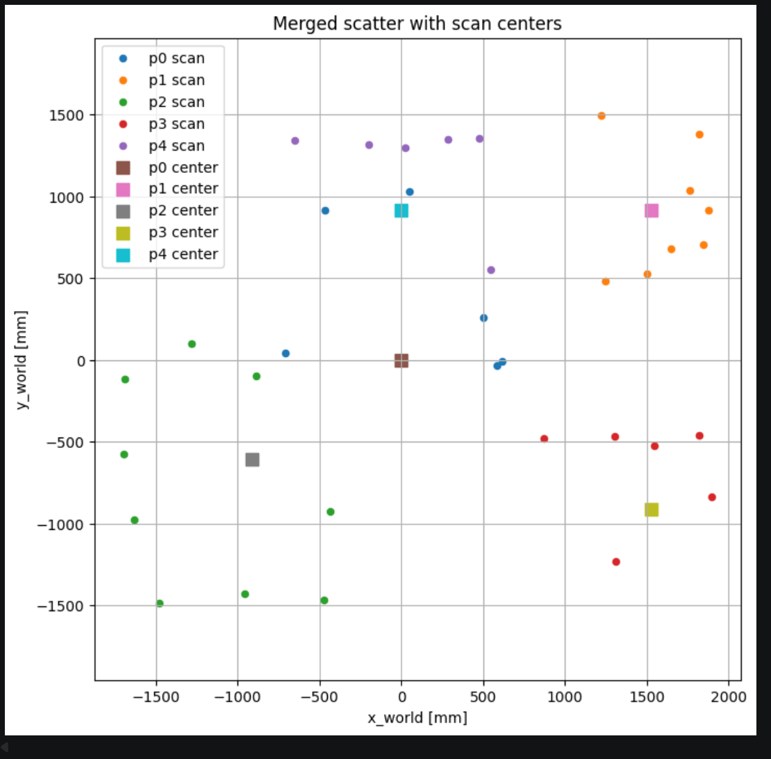
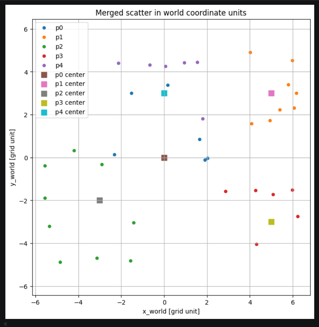
After obtaining the single-point scans, each valid ToF measurement was converted from polar form into local Cartesian coordinates using the measured yaw angle at that sampling instant. The local point sets were then shifted into a common global frame according to the known scan-center positions of the robot, namely \((0,0)\), \((5,3)\), \((-3,-2)\), \((5,-3)\), and \((0,3)\). This transformation allowed the measurements collected from different viewpoints to be visualized in the same coordinate system and compared directly.
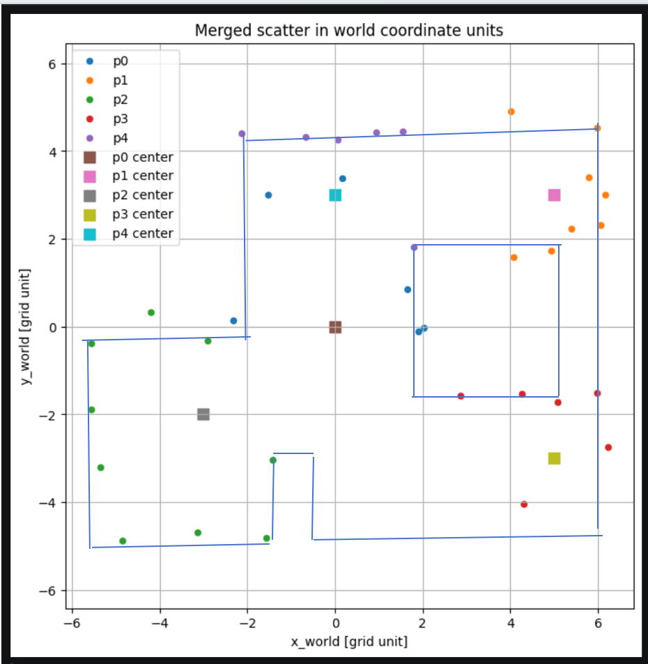
Figure 11 shows the merged global scatter plot, where the measurements from all five scan locations are overlaid in millimeter units. Figure 12 additionally marks the scan centers, which correspond to the known robot positions used during data collection. Figure 13 presents the same merged result in world-coordinate grid units, making the spatial relationship between the scans easier to interpret. Finally, Figure 14 shows a line-based approximation drawn on top of the merged map. Although the reconstructed boundaries are not perfectly aligned with the true room geometry, the overall structure is consistent with the real layout and demonstrates that the multi-position scan data can be fused into a usable global map.
3.3 Discussion of Map Quality
The final merged map captures the overall structure of the room reasonably well, but some portions of the boundary are still sparse or incomplete. One main reason is that several scan locations produced only around six valid ToF measurements, which reduced the density of the point cloud and made some local wall segments less clearly defined. As a result, the reconstructed map does not perfectly match every wall boundary, but the main layout and approximate room shape can still be identified.
In addition to the limited number of valid ToF returns, small mapping errors may also come from slight robot translation during in-place turning, missing ToF measurements at certain headings, and small inconsistencies in initial orientation or coordinate registration between scan locations. Even with these limitations, the scans from multiple marked positions were successfully fused into a common world frame, and the resulting map is sufficiently consistent to demonstrate that the mapping task was achieved.
Appendix
1. An announcement of AI usage
I used AI tools to support parts of this lab, mainly for webpage/HTML formatting, minor code edits and debugging, and polishing the written explanations for clarity and conciseness. Throughout the assignment, I verified the suggestions against the lab requirements, tested changes on my own setup, and made final design and implementation decisions independently based on my own understanding.